MP 2x00 Resassembly

DEDeutsche Version dieser Seite

If you haven’t even disassembled your precious Newton, please click here for the disassembly instructions.

This page is currently under construction. I published this draft because many people have asked me to. Make sure you load the latest version if you want to take apart your Newton MessagePad 2000 or 2100.

Click on the images to get a larger version in a new browser window.

Of course, reassembly is the same as disassembly, only in the reverse direction. It wouldn’t normally require any additional explanations. Unless, of course, your memory is as poor as mine. Or unless you want to make sure your neighbors refrain from calling the cops because you have a frenzied fit. Or unless you don’t exactly enjoy scrolling documents back and forth all the time while you work. After all, most of the following pictures are already loaded, so why not re-use them?
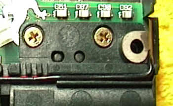
Make sure you turn all screws slowly anticlockwise to find the thread before you turn them clockwise to seat them. Not doing this may cause the screw to become cross-threaded, weakening the plastic post.
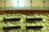
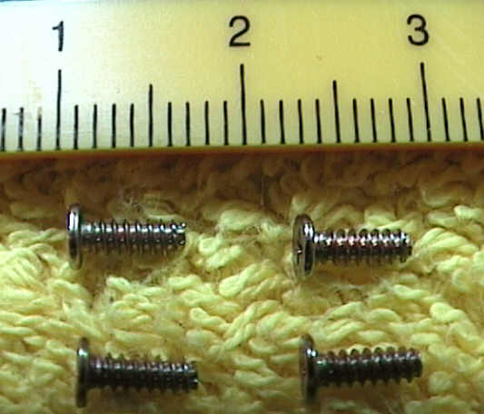
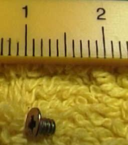
Talking of screws: Here are all the screws you removed.

1 to 4

5 to 9
14 to 17

Left: 10, 11
Right: 12, 13

18

Clean the edges where the display touches the top part of the case on both the display and the case side. Dirt trapped in there is the main cause of what Newton users commonly refer to as “The Jaggies”. This is a typical Newton disease that seems to afflict only the Newton 2000 / 2100 models. Once your Newton is afflicted by the jaggies, it will take to randomly drawing lines on its own when trying to figure out your pen input.

 Thread the touch screen cable through, put the LCD display flat into its plastic counterpart and secure the display with screw 18. Flip the display assembly over.

Clean the top part of the touch screen cable with alcohol and put it back on its two pegs. Do not clean it with anything other than alcohol, don’t use solvents, don’t use anything abrasive. Touching the contacts with your bare fingers is something you would soon regret.

Place the speaker as shown here and thread its wires through their routing channels.

Put the port door back in.

Place the backlight wires as shown here.

Tilt the display assembly as shown in the picture. Hook it on the left (battery) side to engage the three catches. Gently lower it until it lies flat. You will at some time have to push catch B outwards to let the display assembly pass.
Put screws 12 - 17 back in.

Hopefully you will remember where you placed the MLB. Clean its touch screen ribbon cable contacts with a pencil eraser first, then with alcohol. Place all wires (backlight, power switch, microphone, speaker) in a way that they point outwards. We don’t want them caught between the MLB and the case when you put the MLB back in now.
Tilt the MLB so that the battery end is raised and fit the interconnect port plug (next to the ac adapter socket) into its corresponding opening in the case. Do this carefully, the port plug is only fastened by its own fragile soldering joints. Make sure the two touch screen ribbon cable pegs go through the holes in the MLB. There’s also a plastic post which must go through the hole next to the interconnect port plug. Push 
catch B slightly outwards when you push the MLB past it.

Finally, make sure the battery contacts are positioned as before. There is a small metal tab off the outboard side of the contact that should hook over a tiny ridge of plastic in the case. If you fail to do this, you will later have severe trouble with inserting the battery pack, ending up bending that metal tab and shearing off the ridge of plastic.

Put screws 10 and 11 back in. Make sure  catch B is safely engaged. Insert and eject a card in both card slots to ensure the card mechanism works as it should.

Put the battery contact spring back in.

Engage the 5 catches at the bottom side to hook the lower half of the battery case. Press the battery case half towards the bottom (so that it moves away from the MLB) while pushing it down at the same time.

Put screw 9 back in and place the grey microphone wire in its routing channels as shown.

Put the stylus spring catch back in.

When you put the stylus cover back in now, make sure the power switch wires are routed as shown in the picture. They have an annoying habit of ending up a little more to the left, this effectively prevents routing them properly in their routing channels.

Put the stylus cover back in and screw it on with screws 5 - 8. Apart from fastening the stylus cover, screws 7 and 8 have a second job. They ensure that the touch screen ribbon cable is pressed against the MLB. For a reliable contact, tighten screws 7 and 8 as much as you dare. Don’t overdo it, though, otherwise you will kill the thread in the plastic post. If that happens, buy a sixpack, be aware that there are more important things in life than Newtons and go searching for a new case.
Check that the stylus can be properly inserted and ejected.

Route the microphone wire as shown in the picture. There are two clips at the bottom of the MLB that keep it in place. Plug the microphone connector in.
Route the backlight wires through their routing channels in the stylus cover, putting the red wire in first. Plug the backlight connector in, not forgetting to fix it with the clip next to the transformer.
Fix the loudspeaker wires with the black piece of tape and plug the connector in. There are no routing channels to watch out for.
Unlock the display ribbon connector and insert the ribbon cable. Do not touch it while doing so, the oils from your fingers may interfere with a clean connection. Lock the connector and fix the cable with the black piece of tape to the StrongArm IC.

Plug the power switch connector in, making sure that the wires are safely in their routing channels.

If you removed the ROM board, now is the time to put it back in. Say something very nice to your favourite deity. Do it twice again. Flip the Newton around and plug in the ac adapter.
If the Newton powers on, reacts to pen input and has a working backlight, you should get in touch with the aforementioned deity again to say thank you. It never hurts to make sure your luck won’t run out at the last moment..

Put the IR lens in. The right side in this picture must point outwards.

Put the modem connector blank in.

Put the case snap back in. It lives next to the power switch, and the side that points down in this picture should point down (towards the screen) when you put it in.

Put the little plastic part that works the reset button back in. Finally, put the bottom half of the case back in and fasten it with screws 1 - 4.

Dead links? Questions? Anything unclear? Any syntax or grammatical errors in this description? Feel free to tell me about it. Yes, really. Don’t be polite, be helpful. If you aren’t, how am I supposed to improve my English?

Nothing like that? This page really helped you? Wow! What a perfect reason to sign my guest book...

[Home] [Software] [Hardware] [Books] [Stories] [FAQ] [eMail] [Guest Book] [Cry For Help]