2x00 Backlight Replacement

Deutsche Version dieser SeiteDeutsche Version dieser Seite

Recently I came across a very interesting eBay auction. Strictly speaking, it wasn’t me who came across this auction, but someone from Greece whose Newton is currently relaxing on my workbench waiting to be fixed. Isn’t the world of today really amazing? If this nice fellow hadn’t pointed out this German auction to a German supposed to fix his Newton, you, wherever you happen to be, wouldn’t be reading this...
Enough of the preliminaries. This page is about replacing the backlight of the Newton MessagePad 2000 or 2100.
An excellent way to start a Newton backlight replacement project is by taking said Newton carefully apart. Unless you have already done so, make sure to have a look at my Newton 2000 / 2100
disassembly instructions. Once you are through with disassembling your trusty green friend, come back here.
By the way: Clicking on most of the images will open a higher resolution image in a new browser window.

LCD unit disassembledOnce you have extracted the display unit, things should look approximately like this.

Backlight wires lockedThe red and black wires that are attached to the backlight are currently imprisoned under a small clip that keeps them in place.

Backlight wires releasedSlide them towards the bottom until you can pull them out.

Hold down digitizer cablePutting something temporarily onto the digitizer cable to keep it out of the way will make this much easier.

Backlight foil holding clip positionsThe backlight foil is mainly held in place by two small clips located where the arrows indicate.

Backlight foil left holding clip

Just in case you can’t locate the clips: This is what they look like from close-up. The left clip is shown (surprise...) in the left image, the right clip (with the foil already released) is shown in... well... I guess you’ll be able to find that out on your own. The reason for writing that much nonsense here is that I found it aesthetically unpleasing to have only one line of text between the two images.

Backlight foil right holding clip

Flexible printed circuit board left holding clip

The flexible PCB board, not unlike the foil itself, is also held by two clips. This is not without reason: If the PCB is bent or pulled upwards too much while you pull the foil out from underneath it, you have a good chance of killing one or more of the very fragile LCD contacts. Take utmost care to prevent this when you pull the foil out.

Flexible printed circuit board right holding clip

Backlight removal 1Stick something flat like a watchmaker’s screwdriver beneath the backlight foil. Do not stick it in too far, otherwise you will scratch the back side of the LCD display. As long as you can see the tip through the transparent edge of the backlight foil, you are on the safe side.
Slide the screwdriver to the left. In all likelihood the left clip will release the backlight voluntarily once the screwdriver has reached the left corner. If it won’t, persuade it by bending the clip slightly to the left using a second screwdriver as shown in the picture.

Backlight removal 2You can now remove the backlight foil. This is done by pulling it out from under the flexible PCB (towards the bottom of the picture). Be warned of the black sticky tape strip whose job until recently was fixing the LCD ribbon cable to the StrongARM chip on the main logic board. Due to its definitely very poor sense of humor this tape strip considers it extremely funny to stick itself to the backlight foil when it is most inconvenient. If you want to be on the safe side, remove it before you pull the backlight out.
If you want to keep the old backlight for a rainy day, only touch it where the wires end. Never touch it where it faces the LCD display.

Display without backlightThis is how the display unit looks without a backlight. Make sure not to leave it in that unprotected condition for long. It is very eager to collect dust that you’d have a hard time getting rid of.
As for the black tape strip mentioned above, try to be more careful than I was when this picture was taken. If this fellow manages to attach itself to the back of the LCD display (which in my case it fortunately didn’t),  it will make you say things you have always been told not to say. Trying to remove this kind of residue might well leave traces on the display you will never be able to get rid of.

Well, what would a backlight replacement be without a replacement backlight. If you have one from another Newton: Congratulations! But if you don’t, there’s no need to give up. Believe it or not, backlight4you, a company located in Germany, sell brand-new backlights that were specifically made for the Newton 2000 and 2100.
Click
here for details.

The minute I learned about this interesting product, I sent them (at about half past two in the morning) an eMail asking for detailed information. Their reply found my mailbox only 7 hours later. How’s that for customer service!

Outer envelopeThey very kindly offered to send me an evaluation kit. True to form, it arrived a day after they said they had sent it. The kit arrived in a standard bubblewrap-padded envelope.

Inner envelope and floppy diskInside the first envelope I found another cardboard- reinforced envelope along with a weird black rectangular plastic item that also had some metal parts attached to it. Said item turned out to be one of these old-fashioned floppy disks that some of you might still remember.
I’m just kidding, of course. I am not particularly fond of piles of paper sheets with documention that I need only once and never again. Sending the
assembly instructions (pdf, 319 kB) in electronic form is definitely a good thing. However, since many computers do not have a floppy disk drive anymore these days, it might be better to distribute this information on a CD. But this is kind of a moot point anyway: You can always download the most current version from their web site.

I have, by the way, noticed that although my sentences are almost always extremely short and everything I write is generally so concise and to the point that, more often than not, my prose borders on the slightly boring side, my readers have a tendency to forget a very important fact once they are halfway down my very short pages. Please consider this as a polite reminder that you can click on most of the images on this page to get a higher resolution image in a new browser window.

Bag with instructions and backlightOpening the second envelope produced a plastic bag containing one folded sheet of basic information wrapped around the foil. Obviously backlight4you not only wants their shipments to withstand a moderate earthquake, but the average flood catastrophe as well. This kind of excellent packaging is especially important for international shipments. Come to think of it, it is probably equally important for domestic shipments these days. The down side is that it takes a very long time before you can have your first look at your cool new backlight.

BacklightHere we finally have it in all its beauty. The dark parts in the right half are reflections of my camera and tripod.
Make sure not to admire it for too long. It will collect dust just as eagerly as the LCD display. This, by the way, is only a problem on the side that faces the LCD display. Since what you see here is the opposite side, there is no need to remove the label. Just leave it where it is, since trying to remove it will only endanger the foil.

CapacitorDo not throw the bag away just yet. There is a small capacitor attached to it whose purpose I am going to explain in a minute.

Backlight wire connectors 1I was very curious about how the connection to the wires would be solved. This is about the weakest point of all home-grown backlight replacements. But, as you can see, this is not going to be a problem here.

Backlight wire connectors 2To say that this backlight replacement fits well would be an understatement. It fits perfectly. Apple themselves couldn’t have done it better.
backlight4you recommend in their assembly instructions that you should solder the backlight wires to the foil before you put it back in. I do not consider this a good idea. The danger is too big to scratch it or get dust particles on it if it is out in the open for too long. Instead, make sure both the back side of the LCD display and the backlight are absolutely clean. Any dust or dirt that you ignore now will drive you crazy ever after because it will be extremely visible whenever the backlight is on.
Push the foil nearly all the way in. Rotate it slightly clockwise, gently press it down where the
right clip is and rotate it back. This will bring it under the clip without too much pressure. Once it is safely placed, genly press it down where the left clip is until it snaps in. Make sure the flexible PCB isn’t bent and remains snugly below its own two clips.

Unsoldering wires from old backlightRemove the insulation from your old backlight until you can get at the soldering joints. Unsolder the wires. You can also cut them off close to the foil. But, if you do, make sure not to cut off too much because the wires would be too short to be routed properly through their routing channel later. Then remove about 2 mm (0.08 inches) of insulation and tin them.

Preparing solderingPut a piece of paper beneath the foil contacts and bend them slightly upwards.

Soldering wires to contacts
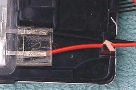
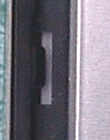
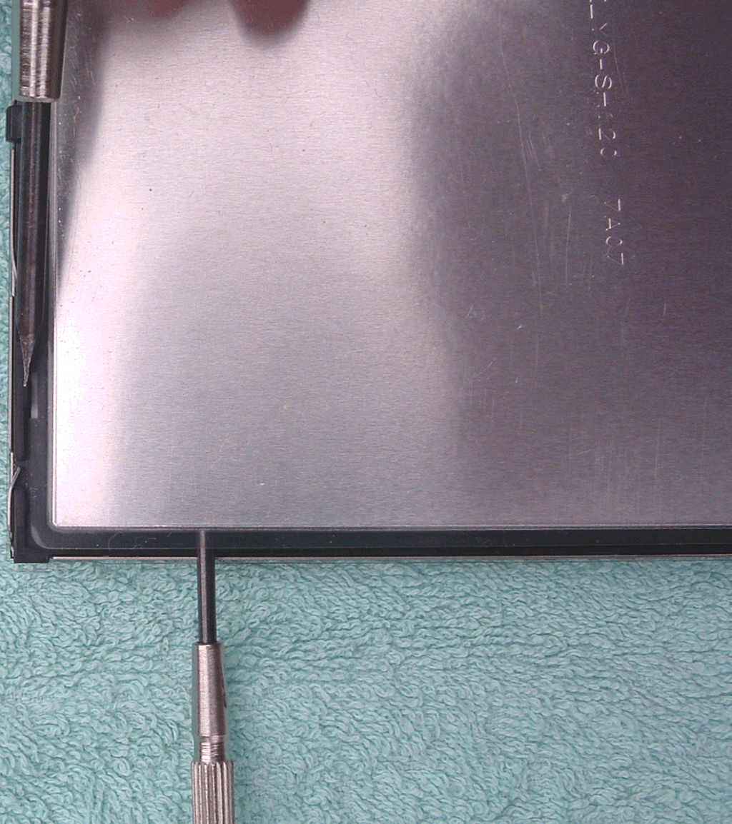
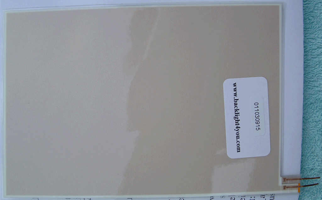
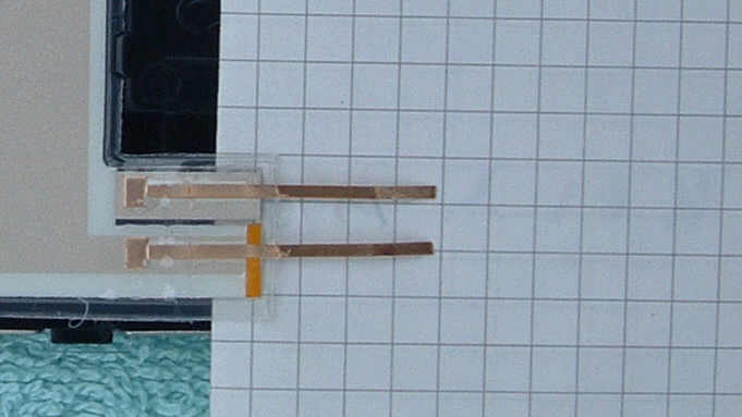
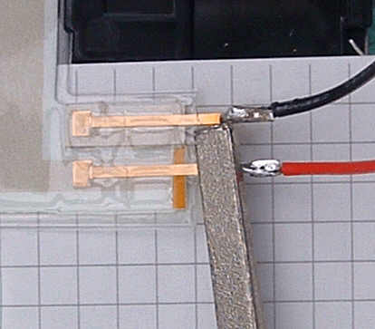
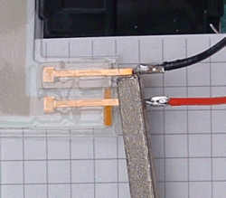
Cut the contacts so that about 5 mm (0.2 inches) remain, i. e. a little shorter than what you see in the picture.
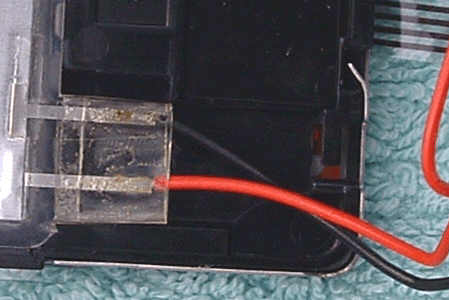
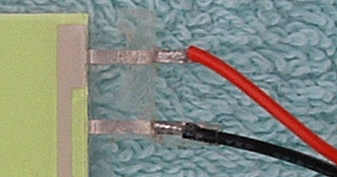
Now comes the most crucial step. If the contacts get too hot, the foil will melt and the backlight will be destroyed. Whatever happens, do not apply heat for more than half a second at a time. If you can’t solder the wire to its contact in half a second, wait a minute and try again. If you have a soldering station that allows temperature adjustment, use the lowest temperature that will still melt the tin. Tin the contacts. Keep the tin on the wire melted while moving the wire towards the contact. Be aware that the wire’s insulation is not going to withstand heat forever, either, so don’t take too much time doing that. Remove the soldering tip as soon as the soldering joint looks good. Using a pair of soldering clamp tweezers (the “inverse” type that stays closed and must be pushed to open them) is an excellent way to get rid of unwanted heat.
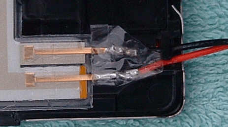
Polarity, by the way, does not matter here because the backlight foil feeds on AC current. Then again, it won’t hurt to solder the wires back on the way they were.
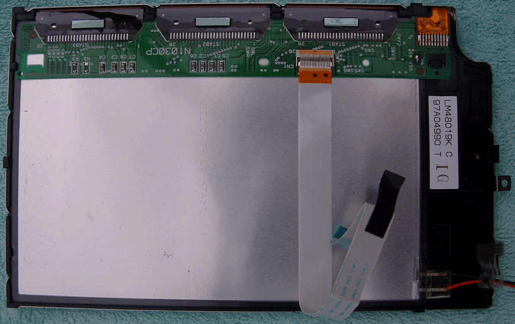
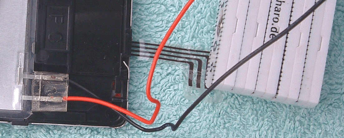
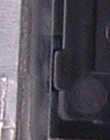
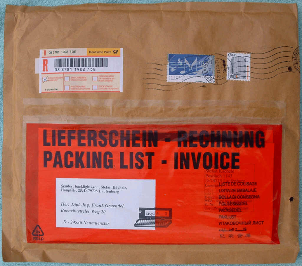
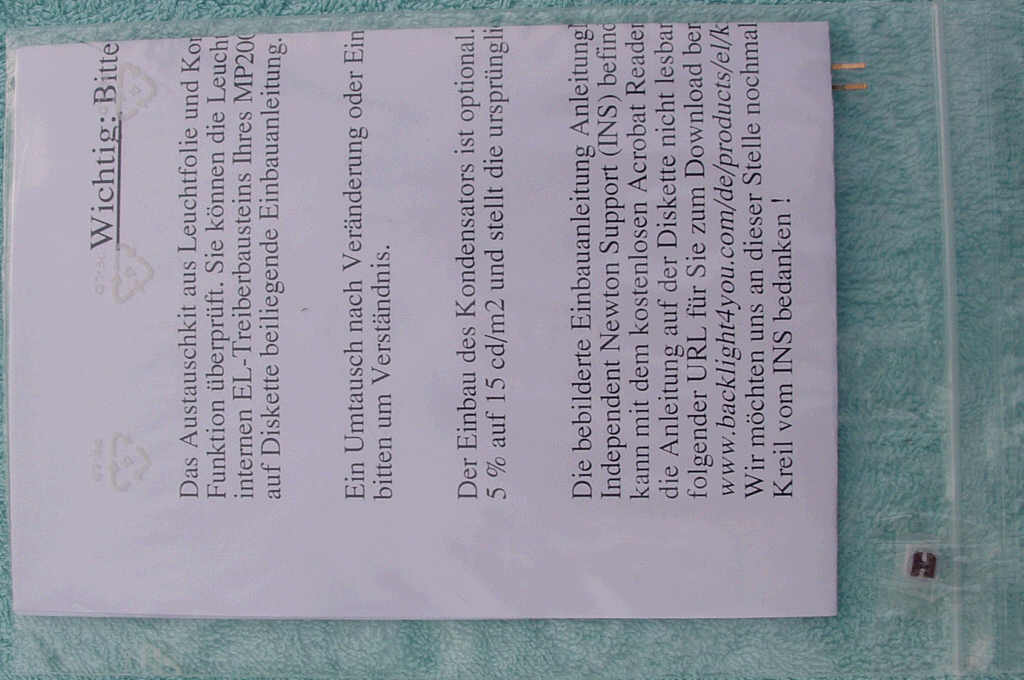
Contact insulationPut some insulation around the soldering joints and slide the wires back below their small rectangular clip that keeps them in place.

Capacitor on PCBUnless the capacitor I mentioned half a mile up on this page has found its way into your carpet by now, you might be interested in the promised explanation of what it is supposed to be good for.
It ensures that the replacement foil will be fed with AC current of the same frequency as before. backlight4you says that this will prevent flicker problems when moving images are displayed and that, apart from that, backlight brightness will increase by about 5 percent.
The good news is that it is not absolutely necessary to replace this component. The backlight will work just fine if you don’t, and I haven’t noticed any flicker problems yet, either. If you feel uncomfortable while soldering tiny surface-mounted electronic components, just put this capacitor on a shelf to be admired ever after and leave the main logic board alone. Doing this kind of soldering is not for the faint at heart, and there is a good chance of destroying the main logic board for good if you don’t have the skills and the equipment to do this professionally.

Capacitor closeup
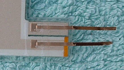
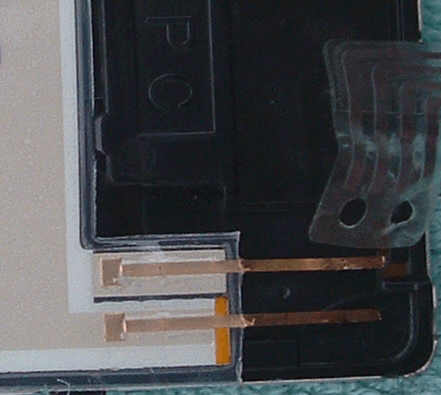
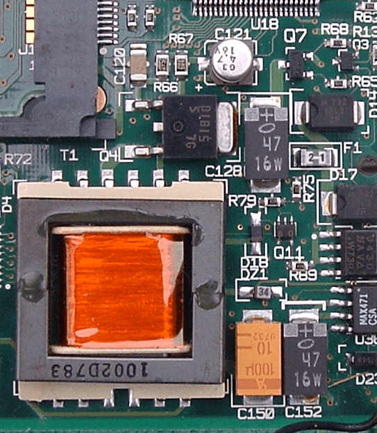
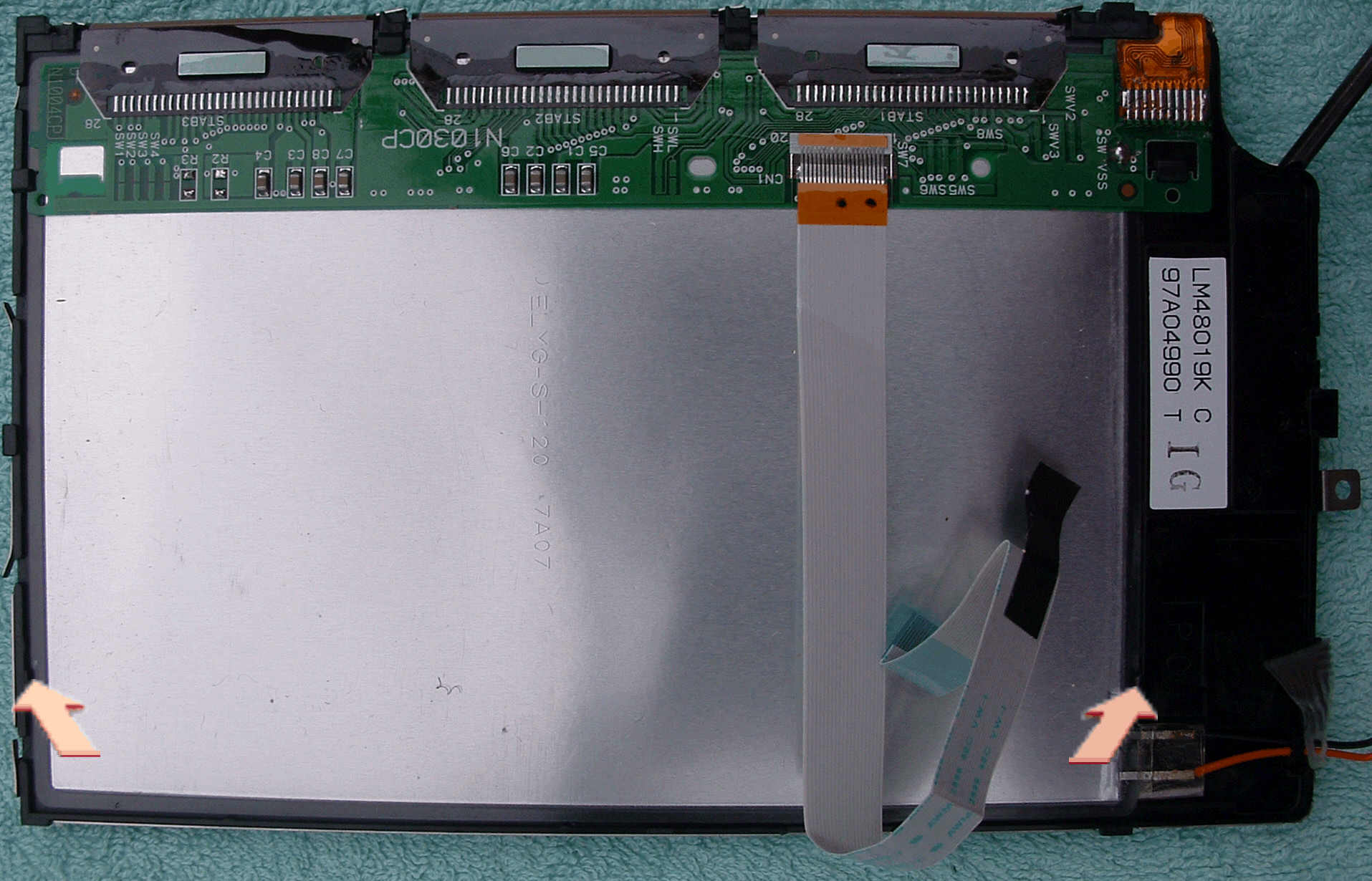
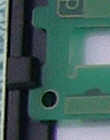
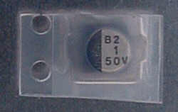
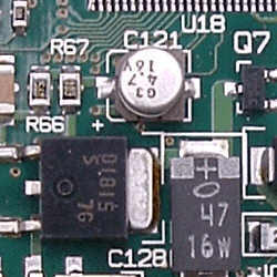
The component we are currently talking about is C121. Although it looks big enough in this picture, it isn’t. It is about 4 mm (0.16 inches) in diameter and about as high. The original is a 4.7 μF capacitor, and it will be replaced with a 1.0 μF capacitor. Polarity matters in this case. The capacitor’s socket has a flat and a rounded side. The positive contact is on the rounded side.

Comparison in normal light conditionForming an opinion on the quality of a backlight replacement is evidently somewhat difficult if you do not have an unused original backlight to compare with. The best I am able to offer is a backlight in a Newton that was in like-new condition when I bought it and has hardly ever been used since then.
The Newton on the left-hand side is the one with the replaced backlight.
backlight4you claims that their backlight is about as bright as Apple’s original. Since I was unable to notice any brightness difference between the two Newtons, this can be believed.

Comparison in darknessConsidering that my camera was fairly expensive and that, apart from that, mounting it on a tripod for only one picture wouldn’t have been worth the effort, I took another picture in total darkness. Although the original backlight seems somewhat brighter here, this wasn’t my impression when I took the picture.

backlight4you ship their products worldwide. This is how much such a project would set you back including insured shipping (prices valid March 2005):

 Germany

Europe

World

 33.80 Euro
 incl. German VAT

37.35 Euro
incl. German VAT

38.19 Euro
excl. German VAT

That’s it. Most likely you will now be interested in my Newton MessagePad 2000 and 2100 reassembly instructions. Or, in the unlikely case that you have given up all hope by now because you consider all this way beyond your skills, you might want to drop me a line. Since one of my few weak spots is excellent single malt whisky, you might even be able to talk me into doing this replacement for you if you choose your arguments wisely...

Dead links? Questions? Anything unclear? Any syntax or grammatical errors in this description? Feel free to
tell me about it. Yes, really. Don’t be polite, be helpful. If you aren’t, how am I supposed to improve my English?

Nothing like that? This page really helped you? Wow! What a perfect reason to sign my guest book...

[Home] [Site Map] [Software] [Hardware] [Books] [Stories] [This And That] [FAQ] [Cry For Help] [E-Mail] [Guest Book] [Legal Info]